Saturday, November 26, 2011

Water Rat Developments

My customer and friend, Ross Trinder from Toowoomba, Australia, has just launched the very first (to my knowledge 10.8 ft length Water Rat. Prior to this there had been a number of the original 9 footer on the water, but Ross' is the first 10.8 ft version.

Ross Trinder's Water Rat 10.8 racked on top of his Green Island 15

Jon Trinder, at 6' 2", gives some proportion to the boat.
Jon seems a big fellow, but the 10.8 version sits high in the water
Ross and Jon Trinder elected to instal a commercial seat
Ross Trinder's beautifully finished Water Rat 10.8

Al Burke has written a couple of nice pieces for Duckworks about his Water Rat here (scroll down to Water Rat) and here (again, scroll down to Water Rat).

Al's Water Rat showing that even the short version can carry a load
Al's wife, Rhonda, showing that the tumble home topsides make paddling easy even though the boat is wide. She is also showing that though Al is an expert pilot as well as waterman, she is better looking than him....
As you can see Al Burke did a top-class job of this Water Rat
Here is a photo of my youngest son, Steve (a long time ago), showing how stable the very first boat was. She was originally designed by my great friend, Doug Laver - I collaborated with the project, but the idea was Doug's and I still call her his design. Since the original, I've worked over the projections and some of the proportions, but as much as possible I've stayed true to Doug's original concept and shape.

More First Mate Activity

Firstly, thanks very much to everybody who wrote in after the previous post. I'm very grateful for the responses, and it helps me a lot in deciding if the information on the blog is relevant to the readership, and gives me some indication about whether I should continue writing the blog.

This week, among other jobs, I've been preparing materials for the hollow "Bird's Mouth" mast for First Mate. The timber I selected is Silver Quandong (Elaeocarpus grandis) which is a light hardwood which grows in the coastal areas of northern New South Wales and in Queensland here in Australia. It is an excellent structural timber for small boat construction, taking both fastenings and glue well, and being suitable for steam-bending. It is the same strength (modulus of elasticity) as Sitka Spruce and is very close to the same weight at 500 kg/cu metre (Sitka Spruce is about 440 Kg/cu metre and Douglas Fir is about 540 kg/cu metre).

The particular stock of Silver Quandong I've got at the moment is unusually dense, and I was concerned that the mast would end up being too heavy. Once the idea got into my head I started having nightmare thoughts, and before long I had convinced myself it was as heavy as Iron Bark and I was ready to throw away two days worth of cutting and machining! In situations like that, the only thing to do is to carry out a test.

All I did was to accurately cut a piece of the material, measure its volume, weigh it, and then calculate the density. The whole thing took me about three minutes using a piece of scrap from the cutting job. The offcut I had on hand was 125.8mm wide, 19.3mm thick, and I cut it to 250mm in length (the sizes are completely abitrary, but must be measured accurately so you can work out the volume). I weighed it on my workshop scales and it came out at 335 grams.

My sample of timber, with the sizes and weight jotted down in red ball-point

0.250m x 0.1258m x 0.0193m = 0.000606985 cu/metre

0.000606985 cu/m = 335gm = 0.335kg

1 cu/metre = 0.335kg/0.000606985cu/m = 552 kg/cu metre

So I discovered that my timber was actually quite light, being about the same as Douglas Fir (Oregon) and lighter than Hoop Pine. Being a very wet 24 hours, the sample was also damp, so its real density is probably a little lower again. The lesson here is not to get fooled by your insecurities - just do a simple test and many problems disappear. I've applied this principle to many things like testing plywood bonds, paint adhesion, bending strengths of masts etc etc. I always use basic equipment for my testing, but the results are fine for the work I do.

Here are a few pictures showing the method I use for cutting "Bird's Mouth" cut-outs: -

Running a mast stave through the table saw for the first cut. Note that I have a homemade finger-board to hold the stave firmly against the wooden saw fence. Accuracy and consistency are important. These staves for First Mate are 16.3mm thick after having been run through a thicknesser.

I finish the cut using a push-stick for safety

This is how the stave looks after the first cut has been completed

Stave has been end-for-ended and the second cut started
The finished cut

Roller-stands are very useful things to have when working alone with long pieces of timber. Ideally, I would like to have a much larger table-saw, or at least a feed-in and feed-out table, but I have neither the money nor the space. However, it is amazing just how much you can do with cheap, second-hand equipment and a buit of determination

Thursday, November 17, 2011

First Mate Progress

As some of you may know, I have a First Mate under construction in my shed. I started her a number of years ago, with the aim of testing the panel developments for the design prior to releasing the plans for sale.


The significance of the need for testing when dealing with developed panel shapes in a stitch-and-glue design is that it is the size and layout of the hull panels which determines the three-dimensional shape of the finished hull rather than relying on an internal skeleton which has been carefully plumbed and shaped, and around which planking is laid.

One is built from the outside-in and the other is built from the inside-out.

Here is a carefully set-up hull on a strongback showing the stem, internal keel (or maybe 'keelson') and a large number of transverse molds around which the planking will be laid. In this case the internal structure determines the shape that the planking will adopt.

In this photo you can see the bottom panel of First Mate having the bilge panels attached using cable ties. The boat is already taking up a three-dimensional shape without any internal framework to help. This system relies totally on the accurate design, marking and cutting of the panel shapes.
This is the very same hull in a photo taken about ten minutes later. The topside panels have been attached with a small number of cable ties and the final shape of the hull has already been defined.

The fundamental difference between stitch-and-glue and any other sort of construction (with the possible exception of Birch Bark canoe building and some forms of Scandinavian "built by eye" lapstrake (clinker) building) is that it is the shape of the cut hull panels that determine the shape of the assembled hull, rather than the rigid internal skeleton as with a conventional boat.

I'm not saying for one moment that one system is any better than another, but rather I am trying to illustrate why it is so critically important that stitch-and-glue hull panels be absolutely correct in their shape.

Hull panels for a scale model of Three Brothers showing how different the flat panel shapes are......

......compared with when the panels are assembled.
 Anyway, to get back to the First Mate that I'm building, once the panel shapes were proven to be correct, there was no urgency in finishing the boat. This may have annoyed my friend Ian Hamilton somewhat since the boat was being sort of financed by him. My boys and I have reluctantly agreed that she may end up being his boat (don't panic, Ian, she is yours...), but there were other things on the books which were more urgent, so First Mate sat in the corner of the shed.

Now the project is up and running again and here are a few photos: -

Foredeck glued into position after having been thoroughly epoxy sealed on the underside. There were three full coats of WEST System Brand epoxy used, with each subsequent coat being applied while the preceding layer was still chemically active, so that a proper bond was obtained. The deck was glued into position while the final coat was still tacky.

Centreboard case treated with epoxy.

Support beams for the stern sheets (aft seat) being treated with epoxy. The inside of the buoyancy compartments have already been treated and thoroughly painted with an epoxy primer/undercoat

Floor of outboard motor splash well glued into position, having been thoroughly sealed underneath

Aft deck being dry-fitted using silicon bronze screws. It was subsequently glued into position using the screws and additional silicon bronze ring nails

Aft seat (stern sheets) glued in after having been epoxy sealed. This view shows how much emergency buoyancy is contained in the sern compartments - this is exactly the same layout as in Phoenix III.

The two 12mm (1/2") plywood centreboard halves being laminated together with WEST System Brand epoxy. In the past I would have vacuum bagged such an assembly, but I lost my compressor in the January floods (the compressor drives the vacuum-generating venturi) so I have had to revert to standard methods. Note the large number of screws which help pull the two laminations together, along with clamps and lead weights. Most importantly, the screw holes allow trapped air to escape so as to give a good, solid bond. The screws are removed just as soon as the epoxy has set, which is the stage you can see in this photograph.

Rudder blade halves being marked out. Note how I have drawn the grid at full-size on the plywood.

Home-cut phosphor bronze plate used to spread the loads from the rudder gudgeon nuts. This is the lower gudgeon mounting viewed from inside the aft buoyancy compartment. It is only dry fitted at this stage, and will be set in bedding compound when fitted permanently.

Marking the top of the rudder blade lamination using a compass

Using a spline to mark out the gentle curves

Using french curves to mark the tight curves

Rudder blade halves spread with WEST System Brand epoxy prior to assembly
Rudder blade halves glued together over a strongback. Note the good squeeze-out, and just after this photo was taken there were bleed holes drilled in the centre portions
I don't know whether these step-by-step photo sequences interest people, so if you feel strongly one way or the other, please let me know. Eventually the website photo pages will get these pictures in thumbnail form, which loads up quickly, and allows you to enlarge only those which are of interest.

Tuesday, November 8, 2011

Responding to some comments

Firstly, a note from my friend, Allan Burke,another from a contributor in Florida, and one from Woody: -

"Rossco, Just knew this design was coming! Ever since I read Munroe's story something keeps stiring inside me about Egret. WHEN I win the lottery you can build US an Egret original,then we'll both know how she sailed. Meantime your new design on the same theme will whet many other appetites I'm sure. There will be much interest in this boat of yours from those who know Egret. Al."

"Something about Egret grabs the soul! Living in coastal florida makes it even closer to home. Anxiuosly awaiting updates, as this design is closer to reality for me than the 28' replica!"

"Lovely! I wonder if the final drawling will be made for the possibility of the occasional night sleeping aboard. Woody"


Well, the customer who prompted the design of this boat has commenced purchasing materials and I hope that we may see some progress in a month or so. I don't think it will be a quick build due to his current workload, but the hull will be easy to put together once the components are assembled.

Construction is from 12mm, 9mm and 6mm marine ply using the traditional skiff construction technique of wrapping pre-cut side panels around frames and bulkheads i.e. no strongback is required. The bottom panel (12mm/1/2" ply) is fitted inside the topside panels flush with their lower edges, and then set in position with glass/epoxy as in stitch-and-glue.

As I mentioned in the original post , this design is not a copy of Egret's lines, but is an attempt to capture her character. The proportions are significantly different, as a direct copy would have resulted in some elements being unsuitable due to the difference in physical size. When drawing the new boat, I did not once refer to the Egret drawings until after I was completely finished.

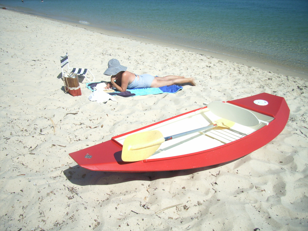
As for sleeping aboard, there is just enough width to have a person sleeping on the floorboards on either side of the centreboard case. Length is not a problem.

I'm very interested to see how this boat goes. She has a small sailplan, but I suspect that she will go much better than many people would expect, and the customer visualises himself poling over the flats in good weather.
_________________________________________________________

"Love Phoenix III and First Mate. Your post prompted me to pull down L Francis' "Sensible Cruising Designs", and the beach cruiser was in the book. Great inspiration. Another of his designs that would make a useful beach cruiser is "Carpenter", built lightly..."

L. Francis Herreshoff's Carpenter - 18' LOA 16'3"LWL 4'6" Beam
From Sensible Cruising Designs - International Marine Publishing, Camden, Maine
I've always been fascinated by the shape and size of Carpenter, and in many ways she would perform the same function as Little Egret. But in my mind, I see Carpenter sailing on blue water off a rugged coast - comfortable under her modest sailplan and with her able and sea-kindly hull giving her skipper confidence....
_______________________________________________________________________

"Great post here in regards to stainless steel fasteners , my dad runs a company that produces them back in the UK, i've always been interested in their applications."

I don't use stainless steel fasteners very much because I am concerned about crevice corrosion. Stainless steel is ok as long as it is 316-grade, and is exposed to a free flow of water or air. But if the flow of air or water is restricted, rust forms quickly. A good example is the common sight of a stainless steel chain plate bolted against the topsides of a boat - the outer surface of the chain plate looks shiny and perfect, but there is a long red rust stain running down the boat where the chain plate is bolted against the hull. If you must use stainless steel, make sure it is 316-grade, and also be absolutely certain to set it in good-quality polyurethane bedding compound.

For permanent screws and nails, I use silicon bronze, but I do make extensive use of 316-grade stainless steel screws and brads for temporary fastening. People ask me why I use stainless if the fastenings are going to come out anyway? The answer is that if one breaks off, at least there is some chance that it will resist corrosion if it is burried in epoxy.
_______________________________________________________________

"Curious as to what design is "waiting in the wings" that may use leeboards. Sounds interesting. Maybe it's the one that will balance with a passenger seated on the aft thwart? Woody"


Well, there is the hull I was talking about. She is the same sort of size as Phoenix III and First Mate, but built either as a strip planked hull, or as a glued-lapstrake (clinker) hull with eight planks per side. The transom is shown vertical, but in the finished drawings it will have 10 degrees of rake. Breadth at the rail has been carried forward so as to allow adequate spread at the oarlocks when rowing from a forward position (yes, Woody, you were correct) and to provide reserve buoyancy. The other reason for carrying the breadth forward is to allow for better mounting of leeboards if that was considered.

These plans won't be available for quite some time, as I am too busy with building work, but I would like to build one for my own use - maybe....
___________________________________________________________________________